

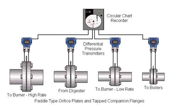
A wastewater treatment plant required a cost effective method to measure and record waste gas flowing from the digesters to the boiler room burners and to a flare stack.
The line sizes, flow rates and pressures for the system are as follows:
|
Waste gas |
Line size |
Flow rate cubic feet per day |
Line pressure |
|
To burner, high rate |
14” |
1,500,000 |
6-9” H2O |
|
From digester |
12” |
750,000 |
6-9” H2O |
|
To burner, low rate |
8” |
500,000 |
6-9” H2O |
|
To boilers |
6” |
250,000 |
3 psig |
The facility’s existing orifice plates and differential pressure transmitters needed to be resized for the current flow conditions.
Orifice plate flow calculations were completed with the new flow conditions. Because of the low line pressure, the orifice plates were sized for a pressure drop of 3” H2O for the lines with 6-9” H2O input pressure and a drop of 10” H2O for the line with the 3 psig input pressure.
Low range differential pressure transmitters were selected to measure the drop across the orifice plates and to transmit a 4-20 mA signal to a 4 channel circular chart recorder. The transmitter signal was converted to a square root within the recorder to reflect a flow rate in cubic feet per day.
The LCD display on the recorder can show the flow rate or total in cubic feet of gas for each input. Each flow rate is also recorded as a line trace on the chart. The total is printed on the chart as a written number with descriptive tags.
For information about the products in this system, visit our products page, or contact us about the products or system of interest.
